Showing all 11 results
-
Sale!
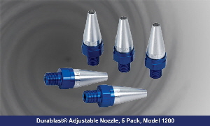
Nozzle with Adjustable Micrometer Dial Model 1200
$107.00 Add to cart -
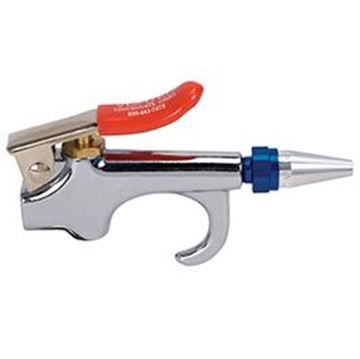
Vortex Model #9401 Air Gun
$44.00 Add to cart -
Sale!
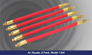
Nozzle mounted on 3/8″ “stay put” flexible hose Model 1204
$224.00 Add to cart -
Sale!
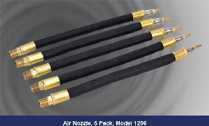
Nozzle mounted on 3/8″ flexible (stay-put) rubber shaft (high thrust) Model 1206
$282.00 Add to cart -
Sale!
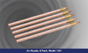
Nozzle mounted on 1/4″ copper tube Model 1201
$180.00 Add to cart -
Sale!
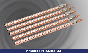
Nozzle mounted on 3/8″ copper tube (high thrust) Model 1205
$243.00 Add to cart -
Sale!
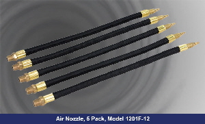
Nozzle mounted on 12” Long 3/8″ rubber shaft Model 1201F-12
$262.00 Add to cart -
Sale!
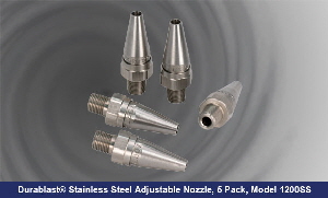
Stainless Steel Nozzle with Adjustable Micrometer Dial Model 1200SS
$272.00 Add to cart -
Sale!
Maximum Thrust Nozzle Model 1220
$265.00 Add to cart -
Sale!
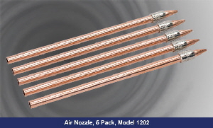
Nozzle mounted on 1/4″ copper tube (high thrust) Model 1202
$194.00 Add to cart -
Sale!
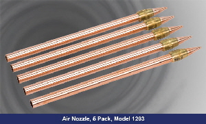
Nozzle mounted on 3/8″ copper tube Model 1203
$248.00 Add to cart
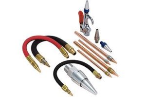 Energy Saving NOZZLES and AIR JETS!

PRODUCT OVERVIEW
Vortec engineered blow off nozzles significantly reduce compressed air consumption and noise, compared to open nozzle jets. Using proven amplification technology, Vortec nozzles entrain and accelerate free surrounding air, resulting in air flow volume up to 25 times more than the volume of compressed air, giving 25 times the blow off capability at a significantly reduced energy usage and lower operating cost. And while reducing air consumption, Vortec nozzles also reduce noise levels by as much as 60%.
Vortec nozzles are available in a full range of designs, materials of construction, sizes and force/thrust levels compatible with most installations; capable of replacing open copper tubes, flex-line, drilled pipe and other nozzles that are not designed to save air. Worker safety standards are met as well, as Vortec safety air nozzles are compliant with OSHA 1910.242(b) dead-end pressure regulations.

Applications:
All air nozzles and jets are not the same. ITW Vortec’s Nozzles and Jets amplify airflow volume up to 25 times more than the compressed air supplied. The result is less compressed air usage to deliver the same or greater thrust performance. Perfect for all types of blowoff, cooling and drying applications, these Nozzles and Jets are available in a variety of low and high thrust models. Use them to meet OSHA compliance as they meet OSHA specifications for noise and dead-end pressure. Additionally, Vortec Nozzles and Jets deliver a very precise airflow making them ideal for parts movement and ejection.


BENEFITS
- Save time with better blow off capability
- Up to 25 times blow off power
- Reduce operating costs due to compressed air usage by up to 80%
- Reduce noise levels by as much as 60% compared to non-amplifying nozzles
- Reach tight spaces with effective blow off
- Better positioning to target with flexible nozzles
- Blow off multiple or changing locations with flexible nozzles
FEATURES
- Full range of designs, sizes and force/thrust levels
- Flexible nozzles allow better positioning
- Adjustable nozzles enable varying power/thrust levels for each blow off job
- Power/thrust levels ranging from 3 – 72 oz-force
- Air stream sizes at nozzle ranging from 3/16” to 1”
- Meet OSHA noise guidelines; reduces noise compared to open copper tubes and drilled pipe
- Meet OSHA 1910.242(b) dead-end pressure guidelines
FEATURES BY PRODUCT
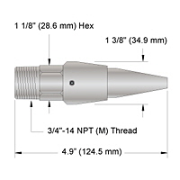
Models 1200 and 1200SS (Package of 5)
- Threaded connection ideal for blow gun and manifold installations
- Adjustable output flow and thrust of 3 – 21 oz-force
- Airstream size of 5/8” at nozzle
- Airstream size of 3 ½” at 12” from nozzle
- Available in aluminum and stainless steel models
Model 1201
- Permanently mounted on copper tubing
- Can be bent , flared, soldered or used with compression fittings. Use 1201F-12 if repeated bending is needed
- Fixed thrust of 6 oz-f
- Airstream size of 3/16” at nozzle
- Airstream size of 3 ¼” at 12” from nozzle
Model 1201F-12
- 1201 nozzle with a flexible rubber hose
- Holds position under full line pressure
- Fixed thrust of 6 oz-f
- Airstream size of 3/16” at nozzle
- Airstream size of 3 ¼” at 12” from nozzle
Model 1202
- High thrust version of the 1201 nozzle
- Permanently mounted on copper tubing
- Can be bent, flared, soldered or used with compression fittings
- Fixed thrust of 20 oz-f
- Airstream size of 3/16” at nozzle
- Airstream size of 3 ¼” at 12” from nozzle
Model 1203
- Permanently mounted on copper tubing
- Can be bent , flared, soldered or used with compression fittings. Use 1204 if repeated bending is needed
- Fixed thrust of 9 oz-f
- Airstream size of ¼” at nozzle
- Airstream size of 3 ¼” at 12” from nozzle
Model 1204
- 1203 nozzle with a flexible rubber hose
- Holds position under full line pressure
- Fixed thrust of 9 oz-f
- Airstream size of ¼” at nozzle
- Airstream size of 3 ¼” at 12” from nozzle
Model 1205
- High thrust version of the 1203 nozzle
- Permanently mounted on copper tubing
- Can be bent, flared, soldered or used with compression fittings
- Fixed thrust of 28 oz-f
- Airstream size of ¼” at nozzle
- Airstream size of 3 ¼” at 12” from nozzle
Model 1206
- 1205 nozzle with a flexible rubber hose
- Holds position under full line pressure
- Fixed thrust of 28 oz-f
- Airstream size of ¼” at nozzle
- Airstream size of 3 ¼” at 12” from nozzle
Model 1220
- Ultra-high, fixed thrust of 72 oz-f
- Designed for large surface blow off
- Ideal for paving, roofing and construction uses
- Threaded connection, ¾” NPT
- Airstream size of 1” at nozzle
- Airstream size of 5” from nozzle
Model 9401
- Blow gun with 1200 nozzle
- Adjustable output flow and thrust of 3 – 21 oz-force
- Ergonomically designed, thumb lever operated
- Convenient hang-up hook incorporated
- Airstream size of 5/8” at nozzle
- Airstream size of 3 ½” at 12” from nozzle
ITW Vortec’s Energy Saving Nozzles and Jets are used for:
- Blowoff of chips, powders, dust, trim scrap
- Cooling or drying parts and assemblies
- Cleaning debris or stripping water and solvents
- Parts ejection and movement
- Replacing open copper tube jets
- Replacing headers with drilled holes
- Energy conservation programs
- OSHA compliance
IMPULSE PRINCIPLE AT WORK
Transvector Jets and Blowoff Nozzles use the same impulse principle described in the Round Transvector section. Compressed air is released at sonic velocity through an annular orifice 0.002”. As the air passes through the orifice, it collides with surrounding air inducing and entraining a much larger mass of air. Blowoff nozzles are designed to maximize the speed of compressed air enabling it to move large masses of secondary air.
TRANSVECTOR BLOWOFF PRODUCTS
Transvector Blowoff products are available as Jets or Nozzles to meet the needs of different applications. Transvector Jets have a round throat design which is similar to the larger Transvectors. Transvector Nozzles provide greater flow amplification with slightly less thrust. Nozzles are ideal for clustering in tight spaces, close to a target because the inlet and outlet are on the same center line.
The high thrust versions provide identical flow amplification with higher thrust. High Thrust Nozzles are ideal to blow away chips, powders, dust and trim scrap in metalworking, woodworking, textile and printing applications, while minimizing air use and cost.
| Features | |||||||
| 1201 Nozzle |
1202 Nozzle |
1203 Nozzle |
1204 Nozzle |
1205 Nozzle |
1206 Nozzle |
1200 Nozzle |
|
| Amplification Ratio | 25 | 25 | 25 | 25 | 25 | 25 | 25 |
| Airstream Size at Nozzle | 3/16” | 3/16” | 1/4” | 1/4” | 1/4” | 1/4” | 5/8” |
| Airstream Size at 12” | 3-1/4” | 3-1/4” | 3-1/4” | 3-1/4” | 3-1/4” | 3-1/4” | 3-1/2” |
| Adjustable | No | No | No | No | No | No | Yes |
| Blowoff Force (ozs.) at 12” | |||||||||
| PSIG | 1201 Nozzle |
1202 Nozzle |
1203 Nozzle |
1204 Nozzle |
1205 Nozzle |
1206 Nozzle |
1200 Nozzle set at: | ||
| 0.006” | 0.008” | 0.010” | |||||||
| 40 | 3.1 | 4.4 | 4.4 | 9.5 | 3.4 | 4.6 | 5.6 | ||
| 60 | 4.9 | 6.7 | 6.7 | 15.5 | 5.8 | 8.0 | 9.1 | ||
| 80 | 6.8 | 10.2 | 10.2 | 20 | 8.6 | 11.4 | 12.8 | ||
| 100 | 8.4 | 20 | 12.8 | 12.8 | 27 | 28 | 10.8 | 14.8 | 16.9 |
| Air Consumption (SCFM) | |||||||||
| PSIG | 1201 Nozzle |
1202 Nozzle |
1203 Nozzle |
1204 Nozzle |
1205 Nozzle |
1206 Nozzle |
1200 Nozzle set at: | ||
| 0.006” | 0.008” | 0.010” | |||||||
| 30 | 3.4 | 5.1 | 5.1 | 10.5 | 5.2 | 6.6 | 7.4 | ||
| 40 | 4.0 | 6.0 | 6.0 | 13.6 | 6.4 | 8.2 | 9.1 | ||
| 60 | 5.4 | 8.1 | 8.1 | 18.8 | 8.7 | 11.0 | 12.3 | ||
| 80 | 6.8 | 10.2 | 10.2 | 23.0 | 11.0 | 13.0 | 15.7 | ||
| 100 | 8.3 | 23.0 | 12.5 | 12.5 | 28.4 | 31.0 | 13.4 | 16.9 | 19.0 |
BASIC PHILOSOPHY
Transvector Jets and Nozzles are airflow amplifiers capable of using a small amount of compressed air to create an airflow several times larger. Basic operating concepts concerning Transvector Jets and Nozzles have been covered in on our pages Round Transvector and Nozzles. Whether noise reduction or energy conservation is the basic aim, blowoff applications of compressed air can be converted to airflow amplification easily using me same philosophies and techniques.
AIR PREPARATION
Filtration
Transvectors incorporate annular openings through which the compressed air escapes. The open areas can be as narrow as .002″. It is essential to filter the compressed air before supplying it to an airflow amplifier. Five micron filtration with automatic draining is recommended. Our Model 701S-36A is an example of an acceptable filter. The cleanliness of the air as it enters the compressor does not indicate its condition at the point of use. Water generated in compression rusts compressed air pipes, and compressor lubricants find their way into the air. Unfiltered air is guaranteed to clog airflow amplifiers, sometimes after only a few minutes of operation.
Regulation
Regulating provides still other advantages. If a nonadjustable blowoff jet is used in different ways (as in an automated machine processing more than one kind of part), the adjustable feature of a pressure regulator will allow setting at the optimum flow for each kind of part. Furthermore, the pressure gauge on the regulator is a convenient way to indicate proper settings and re-establish them for other adjustments. When using Transvectors, there is no reason to limit air supply pressure to 30 PSIG. It is not possible to stop up or block the flow of air, thus, 30 PSIG could never be indicated by a test gauge at the outlet of a Transvector. In fact, Transvectors work better at higher pressures and are often used at 80 PSIG or more without effect on their energy savings and noise reduction capabilities.
Other Air Preparation Equipment
Dryers, lubricators, oil removal filters, and other sophisticated compressed air preparation equipment are not required for Transvectors.
DESIGNING TRANSVECTOR BLOWOFF OPERATIONS
Selecting the Number of Amplifiers
Many open jet blowoffs are 1/4″ diameter or smaller. These often can be fitted with one Transvector Jet or Nozzle and produce good results. Occasionally it is necessary to install more than one Transvector amplifier. It is easy to install a Transvector Jet or Nozzle on a blowgun hose and move it around by hand to experiment for the desired effect. Before testing this way, however, consider the techniques of positioning and aiming discussed below. Multipleinstallations of ampilfiers give you a chance to design the shape of the blowoff stream and tailor it to the target shape. It may be desirable to install more than one amplifier and operate them at lower pressure even though one amplifier at higher pressure might work.
Positioning and Aiming
The total available blowoff force is diminished if the target is too close or too far from the amplifier. Optimum distance for maximum total force is 9″ to 12″ for all models.
There is a correlation between air consumption and total available force. The force experienced by the target is not necessarily the total available force. A 1″ circular target would experience only a small part of the available force if it is placed in a stream 4″ or 5″ in diameter. Amplifiers should be placed closer to smaller targets to try to match stream size with target. “Target,” in the case of chip removal and similar operations, is the area to be cleaned.
Regulator Considerations
The regulator is an important element in attaining maximum efficiency. Nonadjustable products such as the Model 901 Transvector Jet should be adjusted by setting the regulator to the lowest pressure that will provide the desired blowoff effect. This assures minimum air consumption and noise.
The adjustable Models 900 and 909, however, are not the same. For the Flo-gain Nozzle and Set Jet, adjust the regulator output pressure to the lowest expected plant air pressure at the blowoff location. For example, if pressure varies from 75 to 95 PSIG, adjust the regulator to 75 PSIG.
This will isolate nozzle performance from plant air pressure variations. Adjust the Flo-gain’s Nozzle’s or Set Jet’s micrometer adjustment dial for desired blowoff effect. This technique provides the highest operating pressure possible without variation.
Studies have shown that the highest possible pressure associated with the smallest metering gap (dial adjustment) produces the least noise and consumes less air.
Intermittent Operation
Blowoff Jets are often controlled with solenoid valves (example Our 721T-55) to operate only during certain portions of a cycle. When controlling noise or conserving energy, attention to the length of the “on” cycle is important. Although individual installations vary, the “on” cycle should be closely timed to match the stationary time of the target. “On” cycles shorter than this require more air per second and are, therefore, noisier. Longer cycles waste air and add to total plant noise. Short bursts of old style unregulated open jets are not the proper “on” cycle for Transvector blowoff. This is particularly true in part ejection from stamping operations.
CALCULATING COMPRESSED AIR SAVINGS
After Transvectors have been installed and the regulator setting and amplifier dial setting needed to do the job have been determined, the following air consumption data can be used for before-and-after consumption comparisons.
AIR CONSUMPTION (SCFM) CONVENTIONAL BLOWOFF
| Pressure (PSIG) |
2” Long Pipe Nipples nom. pipe size | 1’ Long Copper Tubes nom. tube size |
Holes in Pipe Hole Diameter |
||||||||||
| 1/8” | 1/4” | 3/8” | 3/16” | 1/4” | 3/8” | 1/2” | 1/16” | 1/8’ | 3/16” | 1/4” | |||
| 30 | 39 | 68 | 135 | 5.6 | 16.5 | 45 | 92 | 1.8 | 8.4 | 18.7 | 33 | ||
| 40 | 48 | 83 | 165 | 6.8 | 20.0 | 55 | 113 | 2.2 | 10.2 | 23.0 | 40 | ||
| 60 | 65 | 113 | 225 | 9.3 | 27.5 | 75 | 153 | 3.0 | 14.0 | 31.1 | 54 | ||
| 80 | 83 | 144 | 285 | 11.7 | 35.0 | 95 | 195 | 3.8 | 17.7 | 39.5 | 69 | ||
| 100 | 100 | 174 | 345 | 14.2 | 42.2 | 115 | 236 | 4.6 | 21.3 | 48.0 | 84 | ||
| PSIG /14.5 = Bar: SCFM x 28.3 = SLPM | |||||||||||||
AIR CONSUMPTION (SCFM) TRANSVECTOR JETS AND NOZZLES
| PSIG | 1201 | 1202 | 1203 | 1204 | 1205 | 1206 | 1200 Nozzle Set at | 901 Jet | 901B Jet | 901D Jet | 909 Jet Set at | ||||
| .006 | .008 | .010 | .003 | .006 | .009 | ||||||||||
| 30 | 3.4 | 5.1 | 5.1 | 10.5 | 10.5 | 5.2 | 6.6 | 7.4 | 3.5 | 3.5 | 5.8 | 2.6 | 5.6 | 8.4 | |
| 40 | 4.0 | 6.0 | 6.0 | 13.6 | 13.6 | 6.4 | 8.2 | 9.1 | 4.4 | 4.4 | 7.2 | 3.1 | 6.8 | 10.3 | |
| 60 | 5.4 | 8.1 | 8.1 | 18.8 | 18.8 | 8.7 | 11.0 | 12.3 | 5.8 | 5.8 | 9.7 | 4.3 | 9.4 | 14.1 | |
| 80 | 6.8 | 10.2 | 10.2 | 23.0 | 23.0 | 11.0 | 13.0 | 15.7 | 7.5 | 7.5 | 12.4 | 5.4 | 11.8 | 16.9 | |
| 100 | 8.3 | 23.0 | 12.5 | 12.5 | 28.4 | 28.4 | 13.4 | 16.9 | 19.0 | 9.1 | 9.1 | 15.0 | 6.6 | 14.3 | 21.7 |
| PSIG /14.5 = Bar: SCFM x 28.3 = SLPM | |||||||||||||||
PLANNING A PLANT-WIDE CONVERSION
The Method
After an initial experiment with Transvector Jets and Nozzles, the decision to make a plant-wide conversion to upgrade all blowoffs is still a major one involving careful planning and justification. Use of the following pilot study method will allow projection of plant-wide costs and savings after converting a relatively small portion of the blowoff jets in a plant.
1. Make a complete survey of blowoff jets used in the plant.
2. Calculate blowoff air usage for each jet.
3. Select a representative sample of jets for the pilot study. Five percent of the total blowoff air usage would be appropriate. This selection should be made carefully to ensure the blowoffs picked are representative of most blowoff jets in the plant.
4. Outfit the pilot study jets with Transvector Jets and Nozzles and adjust for proper function.
5. Compare before and after air usage for the pilot study and adjust to full plant air savings potential (multiply by 20 if a 5% pilot study was made).
6. Determine the approximate number of airflow amplifiers, regulators, and filters needed and the approximate maintenance time for plant~wide conversion by scaling up pilot study usages.
7. Justify the project using one of the techniques in the following section.
| Current Method | Proposed Method | |
| Product | 1/4” x 1’ length copper tube | Model 1200 Flo-gain Nozzle at .006” |
| Air Pressure | 100 PSIG | 100 PSIG |
| Duty Cycle | 100% | 100% |
| Consumption | 42 SCFM | 13 SCFM |
| Annual Operating Cost |
42 SCFM x 60min. = 2520 SCFH 2520 SCFH x 16 hrs. (2 shifts) = 40,320 st.cu.ft./day 40,320 SCFD x 250 days = 10,080,000 st.cu.ft./year 10,080,000 SCFYx.26/1000SCF = $ 2,620.80 / year |
13 SCFM X 60 Min = 780 SCFH 780 SCFH x 16 hrs. (2 shifts) = 12,480 st.cu.ft. / day 12,480 SCFD x 250 days = 3,120,000 st.cu.ft./year 3,120,000 SCFY x .26/1000SCF = $ 811.10 / year |
| Annual Cost Savings = $ 1,809.60 / year | ||
| Pay Out Analysis | Cost of 1200 Flo-gain nozzle $14.60 Installation Cost (est.) $ 30.00 Total $ 44.60 Installed cost / annual savings = .017 pay-out factor .017 x 365 days = 6.205 days pay-out |
Justification
The most common means of justifying is based on compressed air savings. Compressed air costs between 20 and 30 cents per 1000 cubic feet. If you haven’t developed costs specifically for your plant, use $ 0.26 per 1000 ft3 Take total projected CFM savings times minutes plant works per year times $ 0.26 per 1000 ft3 for annual savings. Compare with nozzle costs and installation costs to get payback time, return on investment, etc.
It is also possible to justify adding Transvector blowoff by showing that new compressors will not be required. Any capital savings of this type are in addition to the compressed air savings mentioned above.