Free shipping on all orders over $150! Use coupon code FREESHIP at check out
CONVEYING
C.C. Steven, your ANSWER to compressed air challenges.
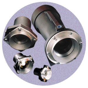
The Round Transvector, Transvector Air Knife and Transvector Air Jet can all be used for the conveying of material and parts.
BASIC PHILOSOPHY
Transvectors are devices that increase the flow of air. Basic operating concepts concerning Transvectors have been covered in our Round Transvectorpage. Transvectors can be specified for cooling and venting or wherever gases or light, finely-divided materials (such as smoke, fumes, particles, resins, droplets, or air itself) must be transported from place to place using a compressed gas as the power source.
TRANSVECTORS ARE NOT…
A Transvector is not a venturi, or an ejector, or a Coanda air mover. A venturi is a necked down section in a pipe with a pressure tap at the throat. A small reduced pressure is obtained at the throat due to the increased speed of the main stream of gas. Venturis are not normally used in suction applications.
Ejectors are devices which discharge a small high speed jet of air inside a conduit. This high speed jet entrains air from its surroundings and causes a larger flow of air to occur. A typical ejector might be able to entrain 3 times as much air as its primary jet thus producing an amplification ratio of 4:1.
Ejectors are high suction, low flow devices. Ejectors are often superior when higher vacuums are required, but not as effective as Transvectors when large flows are required. Ejectors are usually extremely noisy.
Air movers using the Coanda effect have been around for many years. They were invented in the 1930’s and are now considered outdated. Coanda air movers outperform venturis and ejectors, but fail to match the performance of Transvector airflow amplifiers.
Transvectors have basic amplification ratios of up to 25:1, (larger than the ratios produced by venturis, ejectors or Coanda airmovers). Transvectors are extremely quiet, produce small suctions, and are classed as high flow, low suction devices.
They are excellent for many industrial uses involving air conveying quantities of light materials such as smoke, fumes, light particles, resins, water spray, or air itself.
INLET PRESSURE
Transvectors respond to various inlet pressures in a manner similar to Vortex Tubes. Compressed airflow through the nozzle is proportional to absolute inlet pressure for all inlet pressures over about 20 PSIG, because the velocity of air moving through the nozzle is the same at all pressures 20 PSIG and higher, (sonic velocity). Mass flow through the nozzle is then proportional to density which is proportional to the inlet pressure. Thus, the compressed air consumed by a Transvector at 50 PSIG (65 PSIA) is half the consumption of the same unit at 115 PSIG (130 PSIA).
By controlling the pressure supplied to the inlet of a Transvector, it is possible to vary its output flow over a wide range, duplicating the functions of complex variable-pitch and variable-speed fan systems. Transvectors have no moving parts and do not require complex controls. In automated systems, the pressure regulator can be pilot operated and controlled from a remote location.
Since the amount of airflow required in any application is usually not known when the Transvector is selected, it is recommended that a pressure regulatorbe used. This will ensure that the Transvector is set to consume only the amount of compressed air required and no more.
Line Sizes
Up to 12 SCFM, (Model 912) runs of pipe less than 10 feet long may be 1/4″ size without excessive pressure drop. Up to 50 feet, use 3/8″ pipe, and use 1/2″ pipe over 50 feet. Rubber hose of suitable pressure rating may be used. Consider 3/8″ I.D. hose to be the same as 1/4″ pipe, and 1/2″ I.D. hose to be the same as 3/8″ pipe. Remember that lower transmission pressures will exhibit even greater pressure drops, so care must be taken to avoid large losses in the inlet air piping.
Compressor Size
In most large plants, the size of the compressor is adequate to handle many Transvectors operating simultaneously. For smaller plants, estimate horsepower required based upon the rated capacity of the Transvectors. For a 100 PSIG system, it takes one horsepower to compress 4 SCFM of air.
PREPARING THE AIR
Moisture
All compressed air systems will have condensed water in the lines unless a dryer is in use. To remove condensed water from the air, a five micron Auto Drain Filter Separator is recommended to be used with all Transvectors. Place the filter separator as near to the Transvector as possible.
Dryers
Normally a dryer is not required for Transvector applications.
Dirt
Because of the water in compressed air lines, there is always rust and dirt present. Vortec’s Filter Separators effectively remove these contaminants by using a five micron filter. With a Transvector, filtering is essential to remove dirt, which could easily clog the .002 slot. Failure to use a filter will cause clogging in a matter of minutes.
Oil
Never use Transvectors downstream of a lubricator. Oil in the air which has been introduced by the compressor lubrication system is usually not a problem for Vortec products, but occasionally older compressors produce very oily air. If the plant air is very oily, use an Oil Removal Filter downstream of the Filter Separator. The Oil Removal Filter removes dirt, water, and oil aerosols with an effective filtration of 0.01 micron.
PERIODIC MAINTENANCE
Transvectors have no moving parts. They are used in applications requiring continuous operation. If the air is properly filtered, no other maintenance should be necessary. One way to verify proper filtration is to inspect the inside of the Transvector periodically, (example: every six months). To do this, remove the four screws which secure the suction inlet to the body, carefully lift out the aluminum gasket, and inspect gasket and nozzle area for collected dirt. A light oily film is not harmful.
DUCTING RESTRICTIONS
Any restriction placed at the outlet or at the suction inlet of a Transvector will reduce its performance. Transvectors will work against small ducting back pressures at either end. They are designed anticipating some back pressure — up to 2″ inches of water column. In many applications, the outlet of a Transvector will be connected to ducting to carry smoke or fumes away. Whenever outlet ducting or ducting in the suction end of a Transvector is used, design the ducting on either end to make its flow resistance less than 2″ water column. This will prevent major reductions in flow performance.
VENTING APPLICATIONS
When ventilating a large tank or other closed space so that men can work inside it, consider the nature of the fumes to be removed. Whether they are heavier or lighter than air will determine how the Transvector should be used. The following suggestions assume a large tank with a hatchway at the top.
For heavier than air fumes, use the suction capabilities of the Transvector. Place it low in the tank in a remote comer. Attach a flexible exhaust tube to the Transvector outlet and run it out of the hatch. As fumes are vented, fresh air will flow in through the hatch replacing them.
For lighter than air fumes, place the Transvector outside the tank near the hatchway. Run the flexible tubing (attached to the outlet) into the hatch and down into a low remote comer. As the Transvector pumps fresh air into the tank, the lighter fumes will be forced out the hatchway.
CONVEYING APPLICATIONS
Transvectors are ideal for conveying light particles which can be carried in a rush of air. Most particulate materials such as sawdust, grain, plastic resins, soap flakes, etc., work well in Transvector conveying systems. The primary requirements are that the material should be dry, light, and finely divided. Occasionally a particularly abrasive material (grit, sand) can cause wear on the aluminum inner surfaces of a Transvector. Conveyed material cannot clog the Transvector orifice.
Material flowing in a tube will slow down because of flow restrictions of the tube. This is true in blow conveying where material to be conveyed is sucked into a Transvector and blown into a tube connected to its outlet. As the conveyed material slows down it can bunch together causing further pressure drops and eventual blocking. Vacuum conveying is normally preferred in long runs. In vacuum conveying, the material to be conveyed is drawn into the remote end of the tube and moves toward the Transvector. In a vacuum conveying arrangement, the air in the tube moves faster as it approaches the Transvector, so bunching and blocking are not possible. Blow conveying is best in short runs.
It is particularly important in conveying applications to consider static electricity. If plastic tubing is used and the conveyed material is flammable, a static charge can build up, causing sparks and possibly fires. Use of conductive (metal) piping will prevent this problem.
Since large volumes of air are used in Transvector air conveying, the material arrives at the end of the conveying run in a rush of air (the Transvector end in vacuum conveying arrangements). Care must be taken to separate the material from the air. If the stream is injected tangentially into a cylindrical receptacle, it can be settled out in a quiet zone at the bottom of the container much in the way a compressed air Filter Separator works. It will be necessary to vent the container.
EXHAUSTlNG APPLICATIONS
The most common applications for Transvector Airflow Amplifiers are smoke and fume removal. Spot welding, arc welding, and solvent tanks produce many of these smoke and fume sources in most plants. The unusually quiet operation of Transvectors makes them ideal for placing near workers.
Conventional methods of smoke and fume removal often involve electrically powered fans, sheet-metal duct work, hoods, etc. A Transvector can be placed near a source of smoke or fumes and supplied with compressed air in minutes. Its output can run through flexible plastic tubing and out a window or fed into the nearest existing exhaust duct even if it is 50 feet or more away.
In exhausting applications, a filter and pressure regulator should always be used. Once the system is hooked up, start with a very low pressure as indicated on the regulator’s delivery pressure gauge (5 PSI). Then run the process which causes the smoke or fumes, to determine if they will be pulled away at the very low pressure. Increase the pressure slowly until all the smoke or fumes are removed. Lock the regulator knob in its position.
COOLlNG APPLICATIONS
A Transvector can easily be used to cool hot parts when these parts are located in a relatively cool ambient conditions. The capacity of the Transvector to cool the parts will be directly related to the total, entrained airflow directed at the part, and the difference in room temperature and part temperature.
The potential cooling capacity of a Transvector greatly exceeds any other means of cooling when part temperature is at least 200F above ambient conditions.
Sign Up For Our Newsletter

A name you can trust. Doing business since 1978!


